Overview
The mechanical team for the 2024-2025 academic year focused on optimizing the present systems on Qubo developed last year. The main systems optimized are the dropper, claw, and vertical camera systems. New pistons and improved placement for the dropper, claw, and vertical camera will improve Qubo's capability with the appropriate competition tasks. The torpedo team made key advancements to give us a pioneering edge in competition with the powered torpedo last year and has continued to improve and refine the design and operation of the system. Key developments made for the autonomous torpedo platform will have an unprecedented impact to have in the competition landscape once complete.
Mechanical
Pneumatics System
Last year's largest mechanical development on Qubo was the implementation of a custom pneumatics system. Compressed air is regulated from a paintball tank into an enclosure containing 12V solenoid valves. Four of these valves direct air to pistons that produce actuations for Qubo's primary end effectors: claw, dropper, and torpedo launcher. Altogether, this system creates a much more reliable method of actuation compared to servos which have shown to be unreliable underwater. Rotational motion is also much less valuable than linear motion, with the team often using complicated mechanisms to produce an actuation that is easily achieved with pistons. With much more space available from a new DVL, it was ideal to put a pneumatic system in its place, built from scratch by the team to learn the engineering process.
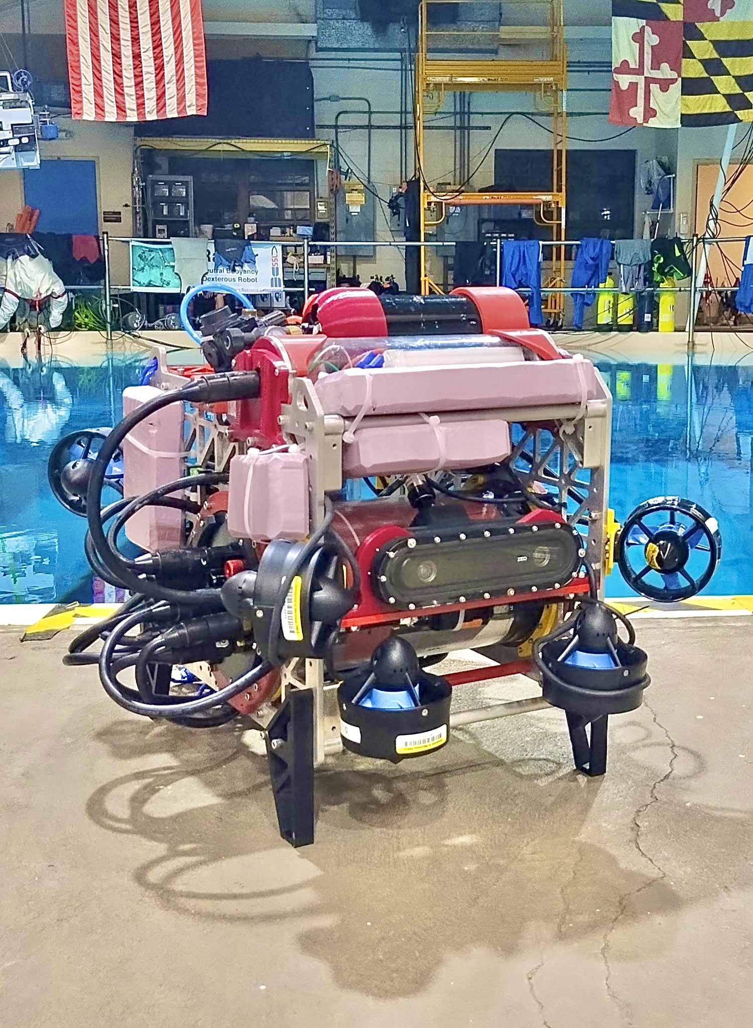
Chassis
The framing we inherited remained unchanged from last year's frame, two main side plates with smaller framing plates and rods connecting the main side plates, aside from cosmetic changes. The bare metal theme of the framing was basic and unattractive so we powder coated all major parts except for the two side plates for a Maryland color theme. While not necessary, presentation is a factor that we had potential to improve on in this year's competition. These cosmetic changes help to bring Qubo together to show that we are one team, Robotics at Maryland.
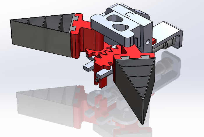
Claw
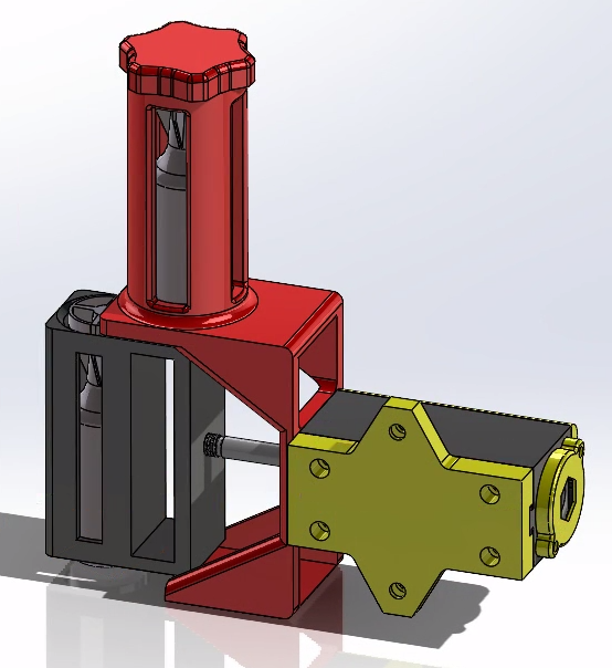
During the competition, Qubo will need to pick up irregularly shaped objects and place them in bins to score points. To do this, we developed a claw that uses a rack and pinion mechanism actuated by a pneumatic piston to open and close. To open the claw, the piston extends and pushes the rack forward. The rack turns the gears and rotates the arms open. The reverse happens to close the claw. The grippers are made of 3D printed TPU and are designed to conform to the shape of whatever they are grabbing. The triangular structure allows them to easily compress and curl around an object. Each gripper has two fins that allow it to slide into the arms of the claw. For the mounting, two brackets securely encase the piston and fasten together with screws that thread into heat-set inserts. The plate on the right side of the claw screws into the inner side plate of the Qubo frame. The claw reaches below Qubo and is able to grab anything it needs to.
Dropper
One task Qubo needs to complete during the competition is dropping a marker into a collection bin below. To do this, we designed a dropper mechanism that uses a pneumatic piston to actuate. When the piston extends forward, it pushes the active cylinder out of the main body. The marker falls down due to gravity. When the piston retracts, the reserve marker falls into the active cylinder. The piston can then actuate again and drop the second marker. The previous iteration of the dropper had a main body that took over 12 hours to 3D print. Additionally, the main body could only be mounted to a specific location on Qubo. The new iteration of the dropper has three separate parts screwed together with embedded hex nuts instead of one large main body. This makes the dropper significantly easier and faster to 3D print if a piece breaks or a design changes. Additionally, the new design's modularity allows the dropper to be mounted almost anywhere on Qubo.
Autonomous Torpedo
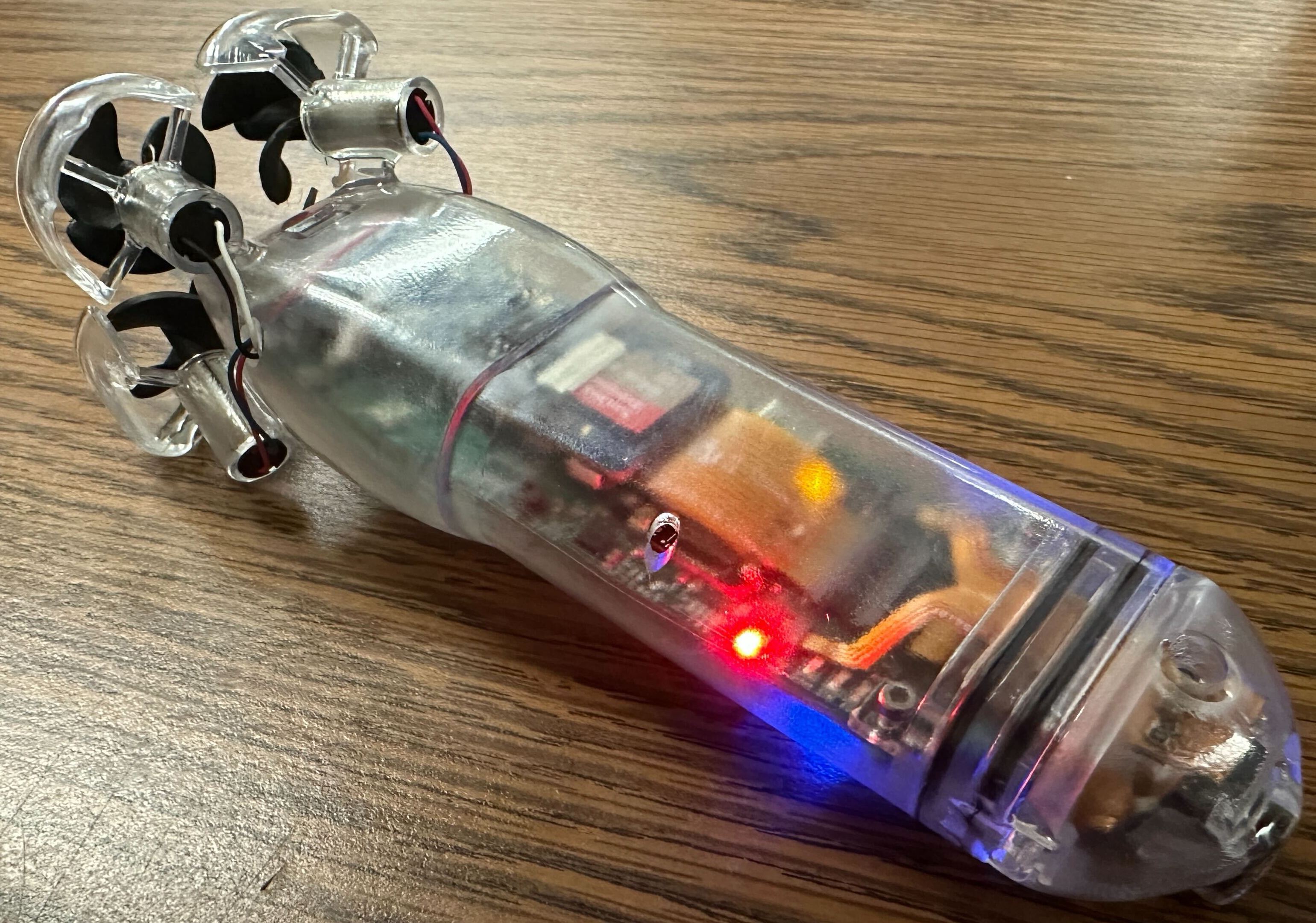
This project had been in the works since the Robosub 2024 competition as a follow up to the powered torpedo. The project statement is simple: A fully autonomous vehicle that fits entirely within the 2x2x6 inch bounding box required for a torpedo (and a marker since they share guidelines).
The design of the autonomous torpedo is split into the body, the head, and the inner skeleton. The body houses the four 7x16mm DC coreless motors, encases the inner electronics, and connects to the head via a double o-ring piston seal and two M2 bolts which keep the parts together. The head is bolted to the skeleton and the PCB allowing all electronics to be accessed once the torpedo is opened. In the head, are two adjustable weights which can be filled with metal for balancing as well as multiple sensors such as the OV5647 camera, I²C pressure sensor and I²C time-of-flight IR distance ranger. The skeleton holds onto the PCB and one-cell 550mAh LiHV battery in order to provide additional structure on the inside of the torpedo.
On the main PCB, an STM32G431 is used as a DC motor controller via PWM, a basic battery manager, and a sensor controller over I²C. The most important I²C sensors on the PCB are the 6DOF inertial measurement unit (accelerometer + gyrometer) and the 3DOF magnetometer which are both used to aid in navigation. The I²C line also extends to the sensor flex PCB and connects to those two sensors. Acting as the brains of the torpedo is the Xiao ESP32 which connects to the STM32 through a separate I²C line in addition to the Grove AI vision model V2 and a 128x32 OLED display for better debugging when the torpedo is in use.
Lastly, the software side of things is slightly less developed, but the STM32's job is separated into a three sections. First it will take a desired heading and orientation from the ESP32 and maintain it according to the magnetometer's reading of north. With four motors in a clockwise/counter-clockwise configuration the control scheme of the torpedo nearly mirrors that of a mini quad-copter drone with 4 degrees of freedom: roll, pitch, yaw, and forwards. Current consumption of each motor is independently read and used to constantly adjust the PWM signal sent to each of the fours DC motor drivers in order to achieve the torpedo's desired heading/orientation. The second job of the STM32 is to read from all sensors and control them as needed. Lastly it will monitor battery voltage and shut down the torpedo once it has dropped too low. All data read from the motor drivers, sensors, and ADC inputs is polled by the ESP32 at a constant rate which computes its next action and then sends a chunk of data back to the STM32.
Powered Torpedo V2
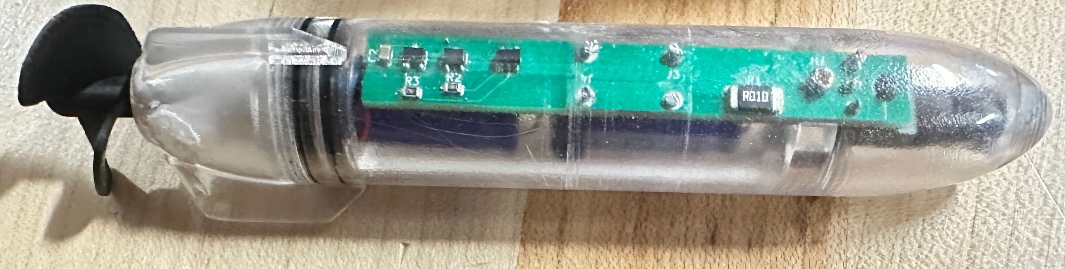
This is the new and improved version of the previous year's design focused on improving reliability and usability. Although this second iteration is largely a backup plan for the autonomous torpedo, the mechanical design has been greatly refurbished. In contrast to last year, the powered torpedo is no longer sealed shut, instead using a double o-ring piston seal to keep its electronics dry and accessible in the case of a failure. Additionally, with the charging port now on the inside there are two fewer hull penetrators to potentially leak water in.
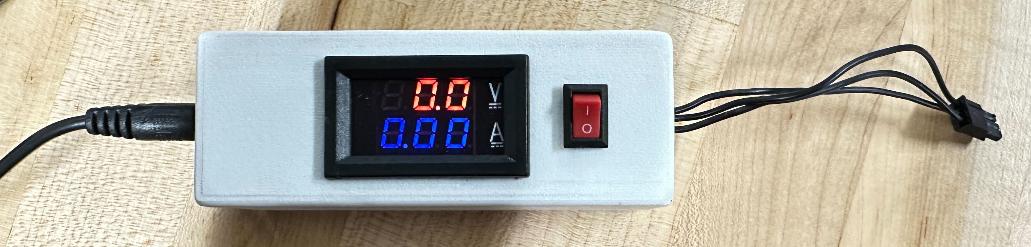
Electrically, it has switched from activating when there is no magnetic field to only activating once the north-pole face of a magnet has moved away. This has greatly improved usability as a magnet no longer needed prevent the torpedo from running when it's charging. Additionally the charging circuitry has been moved out to a custom charger, shown below, which shows the voltage and charging current.
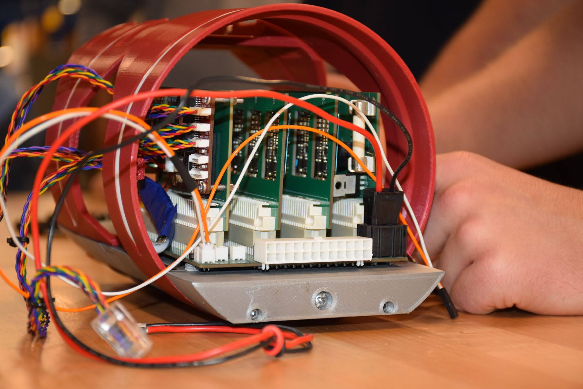
Electrical
Last year's competition saw several new designs implemented on Qubo's electrical hull, from a custom backplane system to a power distribution board. However, it also saw new challenges, including I2C signal attenuation and overheating from the power card. With that being said, the systems implemented on Qubo's electrical hull were largely successful. Considering these factors, many of our new designs for this year's competition were made with flexibility and maintainability in mind. Most importantly, they are entirely backwards compatible. Overall, this year's changes took place primarily on four new and existing boards: the backplane, power card, thruster card, and miscellaneous card.
Backplane
Last year, the backplane was a great solution for reducing wire bulk and increasing modularity. However, it did not include any signal infrastructure, which relied on wires and high impedance WAGOs. In addition, Qubo faced difficulties with I2C signal attenuation throughout its many components. This year, after 14 redesigns, we integrated both I2C and CAN bus signals, with the ability to switch between both options. Moreover, these changes furthered our organizational goals from last year, while also giving us greater flexibility in our choice of signals.
Power Card
Another card we introduced last year was the power card. This card accommodated power supply for 12V, 5V, and 3.3V buses. However, its 12V regulator caused overheating issues on adjacent cards. This year, we have redesigned the power card to have the hot, 12V regulator facing away from other cards. In addition, we created the infrastructure to implement a parallel e-fuse system as a more dynamic alternative to our existing chemical fuse.
Thruster Card
This year, we have also made some major changes to our thruster cards. These thruster cards are essential for Qubo's success, as they are the most direct interface for all of Qubo's motions. Each thruster card now incorporates a new, on-board STM, allowing for enhanced thruster control. In addition, the motor signals were improved, allowing for both CAN and I2C options. Their signal integrity was also improved through use of more unbroken ground planes for EMI shielding.
Miscellaneous Card
There are many miscellaneous systems throughout Qubo's electrical hull that are essential for its success. This year, we have collected these many systems onto a single card, maximizing space efficiency and allowing for easier modifications. Namely, this card eliminates the use of an external Arduino for the LED strips on the hull. In addition, it incorporates a real time clock that will shorten program flash times as our software team makes adjustments.
Software
Our software team focuses on programming Qubo to use our onboard sensors and end effectors so it can autonomously complete the tasks for the RoboSub competition.
Embedded
Our embedded systems act as the bridge between our electrical and software systems. All communication across our variety of sensors, end effectors, microcontrollers, and computers is facilitated by embedded software. Qubo's safety is also managed by this sub group, including current sensing and thruster control.
Navigation and Controls
Using filtering and sensor fusion techniques to efficiently integrate orientation measurements from our VectorNav VN-100 Inertial Measurement Unit, velocity measurements from a WaterLinked DVL-A50 (Doppler Velocity Logger), and depth measurements from our Bar02 Pressure Sensor, we can track Qubo's position as it moves through the water. Independently configurable feedback controllers utilize this full state tracking to manage each axis of movement, combining to produce an overall thrust command sent to our embedded systems that consistently drives Qubo towards its target in all degrees of freedom. This allows us to have Qubo reach positions and orientations accurately and efficiently over a large range and follow desired paths as needed in the process of completing each task.
Computer Vision
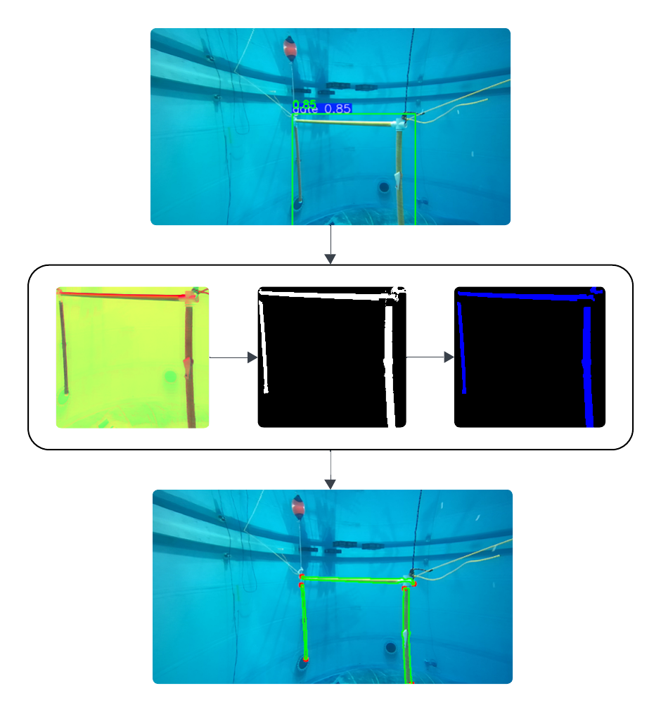
Three exploreHD 3.0 Underwater ROV/AUV cameras (two facing forward, and one facing down) provide us with a comprehensive view of what's in front of and below Qubo throughout each autonomous run. Combining machine learning and traditional computer vision methods, we take advantage of this data to generate information vital to our overall autonomy systems. YOLO models fine-tuned for the RoboSub autonomy challenge cut out parts of each image relevant to the current task being completed. A series of OpenCV methods refine these detections to further identify and isolate important features of the task. Knowledge of the locations of these features and the general dimensions of each task are then incorporated with a depth map from our stereo depth setup to estimate the pose of the task, which is used to calculate target positions for and inform decisions made by our autonomy systems.
Autonomy
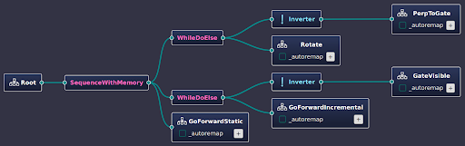
Our autonomy systems are defined in behavior trees, utilizing the BehaviorTree.CPP library. Behavior trees provide a way of translating our high-level plans for each task into easily visualizable and understandable graphs that interact with the rest of our software systems. Each behavior we define takes into account information from our navigation and vision systems so that it can make decisions and send commands to our movement control and other end effector systems in order to complete some part of each task. This framework facilitates define modular behaviors that can be reused across different tasks and makes it easy to change our high-level strategy for each task on the fly as needed.
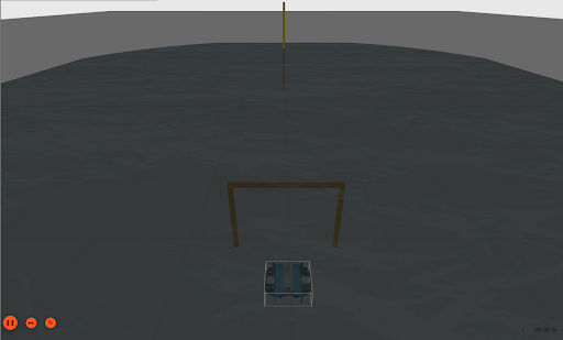
Simulation
Using Gazebo, we are building a simulation of our robot and the competition environment, allowing us to test and refine control and vision algorithms without needing to put Qubo in the water.